Navisworks
Installing the plugin
Simply run the installation wizard which will take you through the plugin installation process.
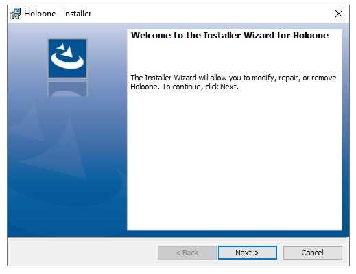
If you already have the plugin installed and are upgrading you will first need to uninstall the existing plugin. Right click on the installer and select Uninstall
You can now launch Navisworks. If the installation process is successful, you will see a tab that says holo|one

Logging In

Users must be logged in to use the holo|one Navisworks plugin.
For customers using the holo|one standalone infrastructure, please use the “Login with Sphere” option. Users will be able to log in using the their holo|one account credentials or Microsoft AzureAD SSO.
For customers using the integrated Lenovo ThinkReality solution, select “Login with ThinkReality” and enter your organization name. This will open a browser window where you can login.
After logging in, you will be able to access the options for Anchor and Export.
Exporting Content
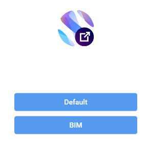
Users have two modes for exporting content which mirror the options available for manual upload using the sphere Management Portal. These include the default 3D model upload and the BIM model upload
For more details on what these different model export modes mean and the different options that are available, please refer to the following page.
https://docs.holo-one.com/mgmtportal/3D-Model-Upload.1003683886.html
Default Export Mode
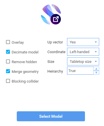
In the default mode, you will be able to select and configure the options for export just like you would on the management portal. After selecting the configuration options, you will be able to select the content for export as well as the output destination. For more details on these steps, see their sections below.
BIM Export Mode
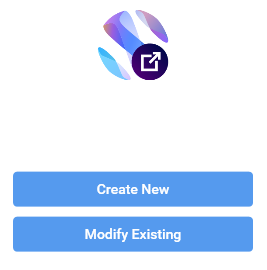
Users of the BIM export mode have the option to create new models or to modify their existing models that have already been uploaded and processed by the holo|one Asset Pipeline. In both cases the options are similar.
Users can provide a name for the model and add as many layers as they want. For each layer, different sections of the Navisworks selection tree can be assigned. Layers that have been assigned geometry in Navisworks are marked with a ![]() and ones that still need to be assigned are marked with a
and ones that still need to be assigned are marked with a ![]() . You can use the ❌ button to delete or remove layers.
. You can use the ❌ button to delete or remove layers.
You will find further information on selecting content for each layer and exporting the final model in the sections below.
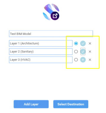
It is also important to set the default layer which is signaled by the radio selection buttons. This is the layer which is used to anchor the model according the reference points. Only one layer can be the default layer.
For more on how reference points need to be set up and used, please see the following page.
https://docs.holo-one.com/mgmtportal/Overlay-Model-Preparation.1339523073.html
Selecting Content For Export
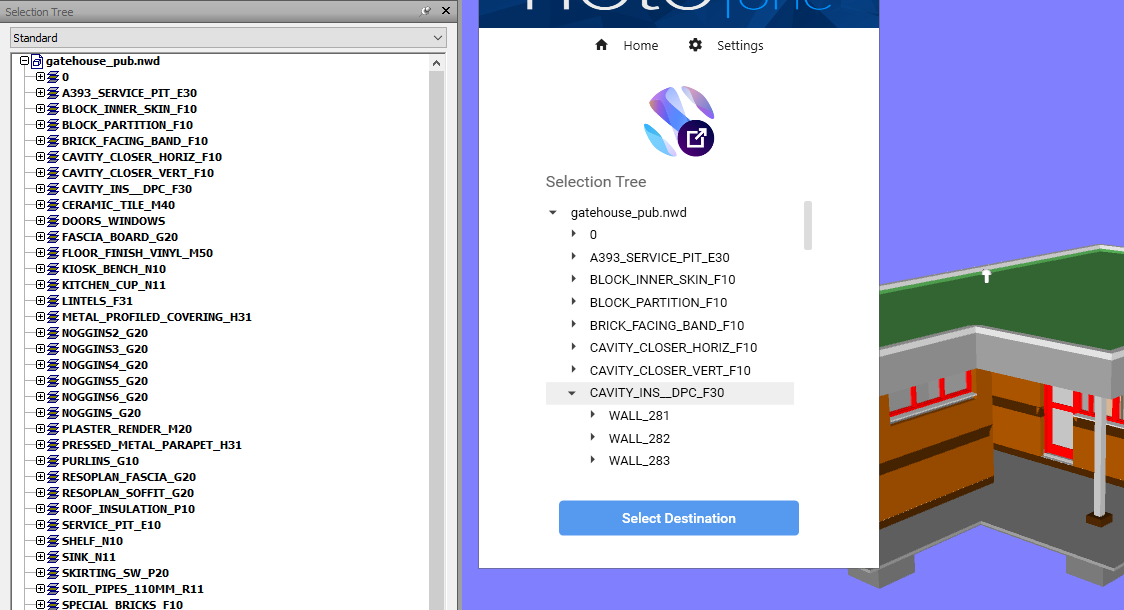
With the Navisworks plugin, you are able to expand and navigate the selection tree of the model, just like you would in Navisworks. Selected nodes are highlighted in gray.
Choosing the Output Destination of the Export
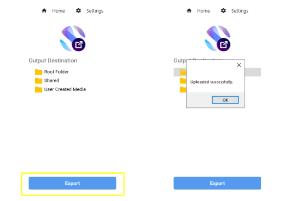
During export, you will be asked to choose the output destination folder to export the file. This is the same process as the sphere Management Portal and reflects the Data Management folder directory structure that is used on the Portal as well as client applications.
Selected folders will be highlighted in Gray.
Adding Anchors to the Default Level
Coming soon!
You will soon be able to add anchors directly through the Navisworks plugin
Anchors must be placed in the default layer in order for the BIM model to be anchored and referenced in space. As a sample, we have supplied two sample anchors that can be used directly (see Downloads below). To create more, simply copy and paste the existing file and give it a new name. You can also use your own anchors provided that they start with the name “sphere_anchor”. To set up these anchors as reference points, follow the procedure below.
It is important to ensure that anchors are placed as children of the layer you want to export to make sure they are included
First import your desired default layer. In this example we will use a simple house.

Append the two anchors to the scene so that they appear next to the model as sibling objects

Move the anchors to the desired location you would like to place them. The easiest way to do this is my measuring between points and applying the correct offset
Select the point-to-point measurement tool (
Review→Measure→Point to Point)Measure from the current anchor position to the desired anchor position, usually on a model surface
To focus either the Anchor or model, use the Focus on item (
Right Click on selection node→Focus on item)
Note the measured distance between the anchor and its target position
Apply the offset using the Units and Transform option to move the anchor to the desired position (
Right Click on selection node→Units and Transform). Keep in mind that the measurement is an offset from the current position and the Units and Transform options are absolute. You can only use direct values from the measurement if the origin is currently at (0, 0, 0).
Repeat the process for any additional anchors (referencing requires a minimum of two anchors)
Export the scene as a new .NWD file to collapse everything into a single node. The anchors must exist as children of the exported layer and not siblings.

Congratulations, you know have a base default layer that contains embedded reference points